简体中文
 ENGLISH
| Fisher Positioners - Supply Pressure & Air Consumption Calculation | ||||||||||||||||||||||||||||||||||||||||||||||||||||||||||||||||||||||||||||||||||||||||||||||||||||
| Release time:2026-11-23 01:35:36 | Views: | ||||||||||||||||||||||||||||||||||||||||||||||||||||||||||||||||||||||||||||||||||||||||||||||||||||
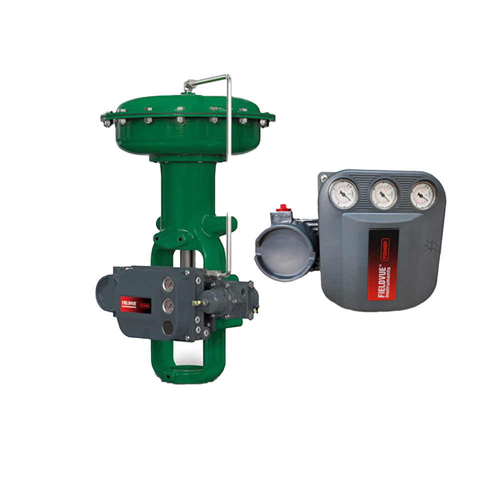
Instrument air system sizing depends on two quantities: the steady-state air consumption of the positioner and accessories, and the peak flow demanded during actuator motion. Fisher DVC data sheets give steady consumption and maximum output capacity. This article organizes supply pressure requirements, air quality, how to read consumption figures, and the sizing logic for regulators and volume boosters. I. Product Positioning
Source: Fisher DVC6200 manual D103409X012; DVC6200 SIS manual D103557X012; 2625 manual D100348X012; 67C/67D manuals 5469/5858.
II. Supply Pressure and Air Quality Requirements
Source: Fisher DVC6200 manual D103409X012 (Table 1-2); DVC6200 SIS manual D103557X012 (Table 1-1). III. Steady-State Consumption Figures
Source: Fisher DVC6200 manual D103409X012 Table 1-2; DVC6200 SIS manual D103557X012 Table 1-1. Steady consumption is read from the table at the actual supply pressure and represents the continuous baseline, excluding transient flow during motion. For a group of instruments, sum the individual steady figures and add a margin; the low-bleed relay (LB / SIS) can significantly reduce long-term operating cost. IV. Peak Flow and Actuator Volume
Source: Fisher DVC6200 manual D103409X012; 2625 manual D100348X012; VBL manual D103393X0CN; SS-263 manual D103592X012. Method: estimate mean flow from actuator swept volume and target stroke time, compare with the positioner maximum output, and add a volume booster of suitable Cv if insufficient. A booster cannot replace a positioner; oversizing can destabilize the loop, so adjust the bypass per the manual. Actual figures are subject to the actuator and booster official manuals. V. Air Treatment and Selection Guide
Source: Fisher 67C/67D manuals 5469 / 5858; 2625 manual D100348X012. Red line: the 67CFR has 1/4" NPT connections only and must not be used as a high-flow header regulator; use the 67D platform for 1/2" high-flow duties. All consumption figures are catalog upper bounds or averages; actual values are subject to the nameplate and official manuals, and project-specific consumption is not invented. Selection guide: Calculation order: set supply pressure and quality, read steady consumption, estimate transient flow, then select regulator / filter / booster. Steady consumption determines long-term cost while transient flow determines whether the valve strokes in time; neither can replace the other. Common models: DVC6200 standard or low-bleed relay (LB), DVC6200 SIS; with 67CFR (single instrument, 1/4" NPT) / 67D (header, 1/2"), 262K filter; add 2625 / VBL / SS-263 if stroke speed is insufficient. If you are sizing an instrument air system, experiencing slow valve stroking, or unsure whether to specify a low-bleed relay or a volume booster, please share the actuator model, stroke time, supply pressure and valve count. We can separate steady consumption from transient flow and review them together. Orders & InquiriesBaoman Industrial Technology (Chengdu) Co., LtdTel: +86 028-60220547 | Email: info@bit-cd.com Address: Room 1108, Building A, Tingbiao Central Plaza, No. 158 Erxianqiao East Road, Chenghua District, Chengdu, Sichuan Province, China The information above is not guaranteed to remain valid at all times. Subsequent changes will not be notified separately. Please confirm the latest information at the time of inquiry. |