简体中文
 ENGLISH
| Pneumatic Volume Boosters & Relays - Working Principle & Selection | |||||||||||||||||||||||||||||||||||||||||||||||||||||||||||||||||||||||||||
| Release time:2026-11-22 09:38:23 | Views: | |||||||||||||||||||||||||||||||||||||||||||||||||||||||||||||||||||||||||||
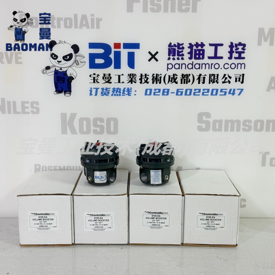
A pneumatic volume booster (also volume booster, flow booster or booster relay) converts a small-flow signal from a positioner or controller into a large-flow output, speeding up the stroke of large-volume actuators. It is not a pressure regulator: the output pressure still follows the input signal 1:1, and only the flow is amplified. Using ControlAir 6100-EA, Fisher 2625/VBL/SS-263 and Masoneilan BR200/BR400 as examples, this article explains the principle, data basis and sizing. I. Product Positioning
Define the requirement first: if the goal is simply to make the valve move faster, choose a 1:1 high-flow booster; if the signal pressure must be converted to a different pressure level by a fixed ratio (such as 1:2 or 1:3), choose a ratio relay such as the ControlAir Type 600. The two are not interchangeable. Source: ControlAir 6100-6200_SpecSheet.pdf (P/N 441-625-069); Fisher 2625 manual D100348X012, VBL manual D103393X0CN, SS-263 manual D103592X012; GE Masoneilan BR200/BR400 manual GEA30642A.
II. Working Principle
Key point: the booster output pressure is uniquely determined by the input signal, so it cannot replace a positioner for precise valve position control. The Fisher VBL manual states explicitly that the VBL only improves stroke speed, that a positioner is required for precise positioning, and that the bypass restriction must be fully closed for pure on/off control. Based on the ControlAir 6100-6200 specification, Fisher VBL manual D103393X0CN and 2625 manual D100348X012, and GE Masoneilan BR200/BR400 manual GEA30642A. III. Key Technical Data
Cv varies with port size in the ControlAir 6100 family: 1/4 in (6100-BA) supply Cv 2.0, 1/2 in (6100-DA) 4.5, 3/4 in (6100-EA) 5.0, and must not be interchanged. Select the smallest Cv that meets the speed requirement; oversizing causes loop instability. Source: ControlAir 6100-6200_SpecSheet.pdf (P/N 441-625-069, port-Cv-pressure-approval); Fisher 2625 / SS-263 manuals; GE Masoneilan BR200/BR400 manual GEA30642A. IV. Sizing Calculation and Installation
Installation notes: (1) the booster and positioner must share one air supply, never separate supplies; (2) supply air must be clean, dry and oil-free, with a high-flow filter upstream; (3) do not use PTFE tape on pneumatic threads (debris can block internal orifices), use thread sealant instead; (4) for SIS service verify the IEC 61508 SIL certificate and area classification; (5) for low or extended temperature ranges check the elastomer option (such as ControlAir options L / P). Formulas are general engineering estimates, not manufacturer guarantees; final selection is subject to ControlAir and Fisher original specification sheets and actuator data. No values are invented. V. Selection Guide and Common ModelsSelection guide: Follow "confirm 1:1 or proportional, calculate actuator volume and stroke time, set Cv and port, set pressure and material, set approvals". Core red lines: (1) a pneumatic booster is a volume booster that reproduces the signal pressure 1:1 and amplifies only flow, it is absolutely not a pressure regulator; (2) when the pressure level must be changed by a ratio, choose a ratio relay such as Type 600, not a 1:1 booster; (3) the booster shares the positioner air supply and the smallest adequate Cv is selected, since oversizing causes loop oscillation; (4) SIL/ATEX approvals are subject to original certificates; if unavailable write "confirm by inquiry". Common models: ControlAir 6100-EA (aluminum, 3/4 in NPT, Cv 5.0/3.5, SIL 3), 6200-ES (316 SS), 6500/6600 (higher flow, Cv 8.0/9.0), Type 600 (ratio relay); Fisher 2625, VBL (VBL-1 to VBL-4), SS-263; Masoneilan BR200/BR400; YTC YT-300 series. If you are selecting a pneumatic booster for a large-volume actuator or an anti-surge valve, or want to decide between a 1:1 booster and a ratio relay or to size the Cv, please feel free to contact us. We can check the model together against your actuator volume, stroke time and supply conditions. Orders & InquiriesBaoman Industrial Technology (Chengdu) Co., LtdTel: +86 028-60220547 | Email: info@bit-cd.com Address: Room 1108, Building A, Tingbiao Central Plaza, No. 158 Erxianqiao East Road, Chenghua District, Chengdu, Sichuan Province, China The information above is not guaranteed to remain valid at all times. Subsequent changes will not be notified separately. Please confirm the latest information at the time of inquiry. |