简体中文
 ENGLISH
| Lock-up Valves - Working Principle & Selection | ||||||||||||||||||||||||||||||||||||||||||||||||||||||||||||||||||||||||||||||
| Release time:2026-11-22 09:38:23 | Views: | ||||||||||||||||||||||||||||||||||||||||||||||||||||||||||||||||||||||||||||||
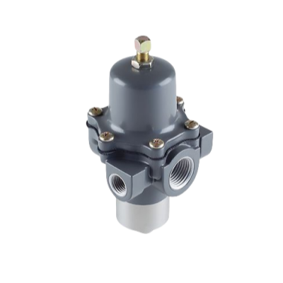
A lock-up valve (also air lock valve or trip valve) is a pneumatic safety accessory installed in the air line of a control valve. When instrument air falls below a set trigger point, it makes the actuator fail in a defined way: fail-open, lock in the last position, or fail-close; when air is restored it resets automatically. This article separates the Fisher 377 pressure-sensitive lock-up valve from the 167D switching valve and explains the principle, trigger setting and sizing. I. Product Positioning
Two concepts must be kept apart: the 377 is a true pressure-sensitive lock-up valve triggered by sensing supply pressure; the 167D is a switching valve whose spool is shifted by a control pressure, and only its three-way version (167DA/167DAS) is used in lock-up circuits. They are often used together but are not the same product category. Source: Fisher 377 series lock-up valve instruction manual (D200319X0CN, 2019), Fisher 167D Series Switching Valves official manual; YTC air lock and switching valve selection data (YTC2020-9-25). Brand ownership: Fisher belongs to Emerson; YTC belongs to Rotork.
II. Working Principle and Fail Modes
Taking the three-way 167DA as an example: control pressure enters at port D and acts under the diaphragm, overcoming the spring to lift the spool, closing C and opening B. When control pressure drops (intentional vent or air failure) below the spring force, the diaphragm and spool move down, opening C and closing B. The pressure change needed for switching depends on the spring and adjusting screw. A typical lock-up system combines a 657 actuator, 67CFR regulator, DVC6010 positioner, air tank, ASCO solenoid valve and a check valve. Based on the Fisher 377 lock-up valve instruction manual (D200319X0CN) and the 167D Series Switching Valves manual; port functions for each configuration are subject to the manual figures. III. 167D Data and Spring Ranges
Common three-way models: 167DA-15 (14-20 psig / 7-20 psig, 1/4 NPT), 167DA-16 (16-35 / 10-30), 167DA-13 (25-60 / 25-50), 167DA-85 (40-125 / 40-90); the 1/2 NPT equivalents are 167DA-9 / -10 / -11 / -81. Select the spring band that covers the actual trigger pressure and verify that the maximum inlet pressure is not exceeded. Source: Fisher 167D Series Switching Valves official manual (ports, pressure, temperature, weight, spring ranges). Order codes and approvals are subject to the official manual. IV. Sizing Calculation and Trigger Setting
Selection steps: (1) define the function - fail in a defined direction selects the 377 series, while simple switching or lock-up selects the 167D (three-way 167DA/167DAS); (2) verify the inlet pressure upper limit; (3) select the spring band by trigger pressure; (4) set the port size; (5) select NBR or FKM by temperature; (6) choose stainless or NACE construction for corrosive service; (7) recheck overpressure protection. SIL3 loops should use certified configurations such as the 377 SST, and NACE service should use the NACE construction of the 167D. Formulas are a general engineering basis, not manufacturer guarantees; tank volume and hold time are ultimately subject to the manufacturer calculation and official manual. No values are invented. V. Selection Guide and Common ModelsSelection guide: Follow "define fail mode, set trigger pressure and spring band, set port and pressure class, set material and temperature, set approvals". Core red lines: (1) a lock-up valve is a lock-up/trip valve, distinct from the 167D switching valve, and only the three-way 167DA is used in lock-up circuits; (2) the trigger pressure must fall inside the process-allowed band - too high causes failure to trip, too low causes nuisance trips; (3) the three-way version has a maximum inlet of only 8.6 bar (6.9 bar for NACE) versus 27.6 bar for the two-way version and must not be interchanged; (4) tank volume and hold time are calculated from actual leakage, and SIL/NACE/ATEX approvals are subject to official certificates; if unavailable write "confirm by inquiry". Common models: Fisher 377 series (377D fail-down, 377L lock last position, 377U fail-up, 377CW/CCW rotary fail) and 167D series (167D/167DS two-way, 167DA/167DAS three-way); other brands include YTC YT-400/405/430/435 air lock valves, Masoneilan 78-80/08-80 transfer valves, SAMSON 3709 (data sheet T 8391). If you are designing a fail-lock or safety interlock circuit for a control valve, or want to decide between a pressure-sensitive lock-up valve and a three-way switching valve or to set the trigger pressure, please feel free to contact us. We can check the model and setting together against your fail mode, air supply and hold time. Orders & InquiriesBaoman Industrial Technology (Chengdu) Co., LtdTel: +86 028-60220547 | Email: info@bit-cd.com Address: Room 1108, Building A, Tingbiao Central Plaza, No. 158 Erxianqiao East Road, Chenghua District, Chengdu, Sichuan Province, China The information above is not guaranteed to remain valid at all times. Subsequent changes will not be notified separately. Please confirm the latest information at the time of inquiry. |
||||||||||||||||||||||||||||||||||||||||||||||||||||||||||||||||||||||||||||||