简体中文
 ENGLISH
| Filter Regulators - Sizing Calculation (Flow / Pressure / Port) | ||||||||||||||||||||||||||||||||||||||||||||||||||||||||||||||||||||||||
| Release time:2026-11-22 09:38:23 | Views: | ||||||||||||||||||||||||||||||||||||||||||||||||||||||||||||||||||||||||
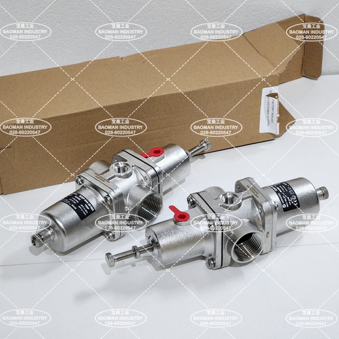
A filter regulator combines filtration and pressure regulation in one body and is the first line of defense in an instrument air or actuator supply system. Sizing is a three-step check: flow (Cv/Kv and flow curves), pressure (inlet, outlet spring range, allowable pressure drop) and port (size and thread), followed by filtration grade, material and drain style. Using IMI Norgren B38P and Fisher 67C/67D as examples, this article gives the general calculation basis and checklists. I. Product Positioning
A filter regulator is not necessarily better with a larger port: the port determines flow capacity, the element grade determines pressure drop and maintenance interval, and the outlet spring range determines the usable regulation band. The correct sequence is to calculate the required Cv/port from flow and pressure first, then return to the data sheet for the exact order code. Source: IMI Precision Engineering B38P datasheet; Fisher 67C instrument regulator manual (pub. 5469), 67D regulator manual (pub. 5858). Brand ownership: Norgren belongs to IMI; Fisher belongs to Emerson.
II. Flow Calculation: Cv, Kv and Line Size
For the B38P, the datasheet states a maximum flow of 4500 L/min measured at 10 bar inlet, 40 um element and 1/2 in NPT. This is not a guarantee at any duty; the actual inlet pressure, outlet pressure and element grade must be checked against the corresponding flow curve. The Fisher 67C (1/4 in NPT) has a main valve Cv of 0.36 and the 67D (1/2 in NPT) Cv of 1.33, so the 67D has clearly higher capacity at the same pressure. Source: IMI B38P datasheet (4500 L/min max and curve test conditions); Fisher 67C/67D manuals (pub. 5469, 5858; Cv 0.36 / 1.33). Formulas are general engineering basis, not manufacturer guarantees. III. Pressure Check and Port Verification
Two hard constraints in the pressure check: (1) supply pressure must exceed the required outlet upper limit by at least 0.5 bar (about 50 kPa), otherwise regulation is lost; (2) inlet pressure must not exceed the nameplate maximum. Check the B38P manual-drain version at 31 bar and the automatic-drain version at only 17 bar. If the inlet can exceed the limit, a separate relief/limiting device is mandatory upstream. The internal relief valve is not full overpressure protection: its Cv is very small (about 0.045 on the 67D). Source: IMI B38P datasheet (17/31 bar, port codes 2/3/4/8, thread A/G, element 1/2/3, temperature codes 4/5); Fisher 67C/67D manuals (pub. 5469, 5858). Unlisted values are subject to nameplate/order or official manual. IV. Sizing Procedure
A common mistake is to interchange flow values between port sizes of the same family (for example 1/4 in 67C and 1/2 in 67D), or to treat the B38P 4500 L/min as a rating at any pressure. The correct method is calculate first, verify second, and rely on official flow curves and nameplates. The procedure is a general engineering basis; order codes and ratings are subject to IMI and Fisher official data sheets and nameplates. No values are invented. V. Selection Guide and Common ModelsSelection guide: Follow the sequence "calculate flow and drop first, set pressure range, set port and thread, set material and element, set drain and temperature, verify order code". Core red lines: (1) flow must be checked on the data sheet curve at the lowest supply pressure and maximum allowable drop, never at the catalogue maximum; (2) supply must exceed the outlet maximum by at least 50 kPa and inlet must stay below the nameplate limit; (3) the 67C is 1/4 in with Cv 0.36, the 67D is 1/2 in with Cv 1.33, and B38P port sizes have different capacities and must not be interchanged; (4) when the outlet regulation range is not listed, write "confirm by inquiry" rather than inventing a value. Common models: IMI Norgren B38P-244-B1MA (1/4 in NPT, manual short bowl, 5 um NBR) and B38P-844-M1MA (1 in NPT, manual medium bowl, 5 um NBR); Fisher 67CFR (1/4 in aluminum economy), 67CFSR (stainless), 67DFR (1/2 in high flow), 67DFSR (stainless). Full order codes are subject to official data sheets and nameplates. If you are sizing a filter regulator for an actuator or instrument air supply, or want to verify that the flow, pressure range and port match, please feel free to contact us. We can check the model and order code together against your air demand, supply pressure and mounting interface. Orders & InquiriesBaoman Industrial Technology (Chengdu) Co., LtdTel: +86 028-60220547 | Email: info@bit-cd.com Address: Room 1108, Building A, Tingbiao Central Plaza, No. 158 Erxianqiao East Road, Chenghua District, Chengdu, Sichuan Province, China The information above is not guaranteed to remain valid at all times. Subsequent changes will not be notified separately. Please confirm the latest information at the time of inquiry. |