简体中文
 ENGLISH
| TOPWORX DXP - Intrinsically Safe Loop Design & Explosion-proof Wiring | ||||||||||||||||||||||||||||||||||||||||||||||||||||||||||||||||||||||||||||||||||||||||||||||||||
| Release time:2026-11-22 09:38:23 | Views: | ||||||||||||||||||||||||||||||||||||||||||||||||||||||||||||||||||||||||||||||||||||||||||||||||||
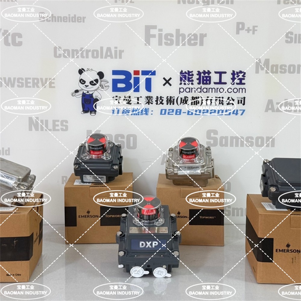
The TOPWORX DXP belongs to the D series of discrete valve controllers. It can be intrinsically safe Ex ia or flameproof Ex d, with the form determined by digit 3 area classification, not by the housing letter D. Intrinsically safe loop design centers on energy limitation and parameter matching: barrier Uo/Io/Po/Co/Lo must not exceed field-device Ui/Ii/Pi/Ci/Li, with cabling, grounding and segregation per EN 60079-14. This article covers the DXP IS loop, area classification, order code and wiring points, strictly distinguishing Ex ia from Ex d. I. Product Positioning
Red line: the DXP is a separate series from the T series TVP / TXP; Ex ia intrinsic safety is not Ex d flameproof enclosure, and their loop design, wiring and cover-opening rules differ completely. Source: TopWorx official discrete valve controller product manual (TOPWORX.pdf). Brand ownership: TOPWORX belongs to Emerson.
II. IS Loop Composition and Parameter Matching
An IS loop may only connect certified intrinsically safe equipment; once connected to a non-IS circuit, the device can no longer be used as intrinsically safe equipment. Source: TopWorx official discrete valve controller product manual (area classification and wiring sections); EN 60079-14 and IEC 60079-11. III. Area Classification and Sensor Compatibility
Define digit 3 from the site area classification first, then check whether the chosen sensor / bus code is permitted in that classification. Verify option compatibility with the official ordering manual after assembling the code. Source: TopWorx official discrete valve controller product manual (D series area classification table 1.3.3). IV. Signal Types and IS Loop Interfaces
IS loop points: prefer low-power signals such as L / Z dry contacts or E NAMUR; with X / H transmitters, account for barrier voltage drop, cable resistance and minimum device operating voltage; for HART, confirm the barrier passes the HART frequency band. Source: TopWorx official discrete valve controller product manual (sensor electrical ratings 1.6 and bus networks 1.7). V. Ex ia versus Ex d Wiring Comparison
The two must not be interchanged; a device that "can be explosion protected" does not mean IS wiring applies to a flameproof model. Where area certification is unavailable or uncertain, write "please consult for confirmation" and rely on www.topworx.com official data sheets and certificates. Source: TopWorx official discrete valve controller product manual (area classification table 1.3.3); EN 60079-14, EN 60079-1 and IEC 60079-11. VI. Selection Guide and Common ModelsSelection guide: DXP IS loop design sequence: set digit 3 from the site area classification (0 = Ex ia, 1 / C = Ex d, 2 = Ex nA, G / W non-hazardous), select a low-power sensor (L / Z dry contact, E NAMUR or X/H transmitter), choose a barrier / isolator matched to the device certificate and check Uo/Io/Po/Co/Lo plus cable parameters, complete routing, single-end shield grounding, marking and sealing per EN 60079-14, then verify compatibility with the official ordering manual. Ex ia and Ex d are strictly distinguished; where unavailable, write 'please consult for confirmation'. Common models: DXP (tropical aluminum), DXR (composite resin) and DXS (316 stainless); common IS configurations use L2 / L4 GO Switch and E2 / E4 NAMUR; flameproof configurations use digit 3 set to 1 or C; ESD / PST applications may select ES (SIL-3). If you are designing an intrinsically safe loop for a DXP, or want to verify barrier parameter matching, area classification codes and Ex ia / Ex d wiring differences, please feel free to contact us. We can check the loop and order code against area certification, signal type and cable conditions. Orders & InquiriesBaoman Industrial Technology (Chengdu) Co., LtdTel: +86 028-60220547 | Email: info@bit-cd.com Address: Room 1108, Building A, Tingbiao Central Plaza, No. 158 Erxianqiao East Road, Chenghua District, Chengdu, Sichuan Province, China The information above is not guaranteed to remain valid at all times. Subsequent changes will not be notified separately. Please confirm the latest information at the time of inquiry. |