简体中文
 ENGLISH
| Fisher Positioners - Instrument Air Quality Requirements & Air Purification Desi | |||||||||||||||||||||||||||||||||||||||||||||||||||||||||||||||||||||||||||||||||||||||||||||||||||||||||
| Release time:2026-11-22 09:38:23 | Views: | |||||||||||||||||||||||||||||||||||||||||||||||||||||||||||||||||||||||||||||||||||||||||||||||||||||||||
Instrument air quality is the foundation of reliable positioner operation. Fisher DVC manuals require clean, dry, oil-free air and reference ISA 7.0.01 / ISO 8573-1 for particles, oil and pressure dew point classes. This article covers air quality limits, the effects of poor air, purification design points and selection of 67CFR / 67C filter regulators. I. Product Positioning
Air treatment is not a minor accessory: particles clog the pilot valve and amplifier, oil swells elastomers and attracts dirt, and moisture freezes at low temperature causing failure to move. Air quality should be the first check in both selection and maintenance. Source: DVC6200 manual D103409X012, DVC6200 SIS manual D103557X012, DVC7K Product Bulletin D104765X012, Fisher 67C / 67D filter regulator selection manual.
II. Air Quality Limits
Wording differs slightly between model revisions, and ISA 7.0.01 coexists with older ISA-S7.3 references. Use the current model manual and the project air specification; do not convert between classification systems on your own. Source: DVC6200 manual D103409X012, DVC6200 SIS manual D103557X012, DVC7K Product Bulletin D104765X012; ISA 7.0.01 / ISO 8573-1 clauses. III. Typical Effects of Poor Air Quality
The DVC6200 is relatively insensitive to supply pressure variation but not zero; SIS and low-bleed relays are more sensitive to air quality. When air problems are suspected, measure actual pressure and dew point at the positioner inlet before assuming an instrument fault. Source: DVC6200 manual D103409X012 air requirements; Fisher instrument supply (regulator / system) technical data. Symptom analysis is engineering judgment; parameters are subject to official manuals. IV. Air Purification Design Points
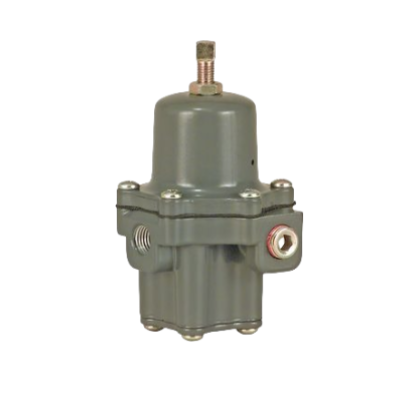
Integrated mounting reduces piping and leak points: Fisher positioners can take a 67CFR integral filter regulator (the DVC7K bulletin lists an integral 67CFR mounting seat on the air inlet), and order code SF denotes a 10 micron inline supply filter. Whether to specify SF depends on site air quality. Source: DVC7K Product Bulletin D104765X012 (integral 67CFR seat, SF option); Fisher 67C / 67D filter regulator selection manual. V. 67CFR / 67C Filter Regulator Selection
Exact Cv, port combinations and approval options for 67CFR / 67C are subject to the official selection manual. If site air quality is good and centralized filtration exists, the positioner may only need the SF integral filter; otherwise install a dedicated filter regulator ahead of it with a defined drain arrangement. Source: Fisher 67C / 67D filter regulator selection manual (official document); DVC7K Product Bulletin D104765X012. Specifications are subject to official data sheets. VI. Selection Guide and Common ConfigurationsSelection guide: Follow the sequence confirm air medium and quality (particles / oil / dew point), confirm supply range and actuator requirement, decide centralized versus local treatment, size the filter regulator (Cv, filtration, ports), verify positioner options (SF / 67CFR seat), and verify approval and ambient temperature. Write subject to official manual / nameplate or please consult for confirmation for unavailable classes and specifications; never invent classification numbers. Intrinsically safe Ex ia loop wiring must follow certified parameters and is strictly distinct from Ex d flameproof enclosure. Common configurations: DVC6200 with integral 67CFR filter regulator (compact, few leak points); DVC6200 / DVC2000 with SF (10 micron inline supply filter); centralized air treatment (dryer plus main filter plus local filter regulator) feeding multiple positioners. If you are verifying a positioner model, spare part or diagnostics level, or want to confirm air purification and area approval requirements, please feel free to contact us. We can check the model and configuration together against your protocol, actuator interface and site approval conditions. Orders & InquiriesBaoman Industrial Technology (Chengdu) Co., LtdTel: +86 028-60220547 | Email: info@bit-cd.com Address: Room 1108, Building A, Tingbiao Central Plaza, No. 158 Erxianqiao East Road, Chenghua District, Chengdu, Sichuan Province, China The information above is not guaranteed to remain valid at all times. Subsequent changes will not be notified separately. Please confirm the latest information at the time of inquiry. |