简体中文
 ENGLISH
| Flowserve Logix Positioners - Working Principle & Configuration Switches | ||||||||||||||||||||||||||||||||||||||||||||||||||||||||||||||||||||||||||||||||||||||||||||||||||||||||||||||||||||||||||
| Release time:2026-11-21 13:41:01 | Views: | ||||||||||||||||||||||||||||||||||||||||||||||||||||||||||||||||||||||||||||||||||||||||||||||||||||||||||||||||||||||||||
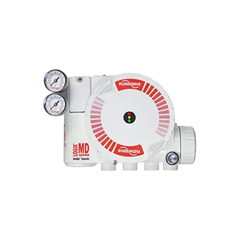
The Flowserve Logix 3200MD / 3200MD+ / 520MD+ are HART digital electro-pneumatic valve positioners built around the chain of "electrical input - electro-pneumatic conversion - valve position feedback closed loop", with local DIP switches, calibration buttons, status LEDs and an optional LCD. This article reviews their working principle, configuration switches and field commissioning / calibration steps, and lists verifiable key parameters. Specific switch positions for each model are subject to the original IOM, and unpublished content is marked "please consult for confirmation". I. Product Positioning
The positioner receives a current command from the control system, continuously compares valve position feedback with the setpoint, drives the actuator through a piezo pilot stage, and settles when the valve position matches the command. The 3200MD emphasizes local DIP switches and dynamic gain auto tuning, the 3200MD+ adds an LCD option and richer alarm diagnostics, and the 520MD+ features piezo technology, an optional LCD and more than 130 alarms. This data was obtained via web search. Sources: Flowserve official pages https://www.flowserve.com/products/products-catalog/actuators-instrumentation/positioners/digital-positioners-logix-3200md-0 , https://www.flowserve.com/node/752 , http://flowserve.com/en/products/products-catalog/actuators-instrumentation/positioners/digital-positioners-logix-3200md/ ; manual references: Logix 3200MD User Instructions (IOM), Logix 520MD+ and 510+ Digital Positioners IOM, FCD LGENIM0105-00. Manual numbers are subject to the latest official releases.
II. Working Principle: Electro-Pneumatic Conversion + Position Feedback Loop
This is a classic negative feedback loop of "input - comparison - amplification - actuation - feedback": the positioner does not simply convert current into air pressure but continuously corrects its output with valve position feedback. Therefore feedback linkage installation quality, supply air quality and actuator friction all directly affect closed-loop performance. Source: Flowserve official Logix product pages and Logix 3200MD / 520MD+ user manuals (IOM); alarm counts and piezo technology data come from official web information obtained via web search (URLs in the previous section). Details are subject to the corresponding model IOM. III. Configuration Switches and Local InterfaceOfficial sources and manuals explicitly mention "DIP Switch Setup" and local calibration buttons on the Logix 3200 family; the 520MD+ user manual lists configuration switches, air action switch, signal at closed switch, characterization switch, auto tune switch and a selectable gain switch. The table below summarizes their purposes; specific switch positions are subject to the corresponding model IOM.
This data was obtained via web search. Sources: Flowserve official Logix 3200MD / 3200MD+ / 520MD+ product pages, Logix 520MD+ Series User Instructions (FCD LGENIM0105-00, public manualslib page); the official "Logix 3200 Positioner DIP Switch Setup" video entry confirms DIP switch setup exists. Unpublished switch positions are marked "please consult for confirmation" and are not invented. IV. Commissioning and Calibration Steps
Recommended commissioning order is "mechanics first, then electrics, then parameters": set up mounting and feedback linkage, then switches and gain, and finally stroke calibration and diagnostics. Whenever a switch position or parameter is uncertain, mark "please consult for confirmation" and check the original IOM rather than trying positions by guesswork. Source: Flowserve Logix user manuals (IOM) and official product pages; gain positions, quick calibration and factory reset descriptions come from publicly available manual pages obtained via web search, subject to the latest original IOM. V. Key Parameters and Ex Boundaries
Ex ia intrinsic safety and Ex d flameproof enclosure are two different forms: intrinsic safety limits energy and normally needs a safety barrier, while flameproof enclosure relies on a housing that withstands internal explosion. The 3200MD is listed with both Ex ia and Ex d versions, so the order code and nameplate must be checked to determine which one applies; when unavailable write "please consult for confirmation" and never summarize them as simply "explosion-proof". This data was obtained via web search. Sources: the three Flowserve official product pages (URLs in section I) and Logix 520MD+ Series User Instructions (FCD LGENIM0105-00); items not explicitly stated on the official web, such as ingress protection and SIL, are attributed or marked "please consult for confirmation" and are subject to original certificates and IOM. VI. Selection Guide and Common ModelsSelection guide: First define the model by communication and diagnostics: HART 5 with basic local operation selects the 3200MD; LCD, more alarms and HART 6/7 select the 3200MD+ or 520MD+. Then check site Ex requirements for Ex ia intrinsic safety, Ex d flameproof enclosure or Ex nA non-incendive, strictly distinguishing intrinsic safety from flameproof enclosure and marking unavailable data "please consult for confirmation". Finally verify housing, interfaces, gain and configuration method, and set DIP switches and calibration steps per the corresponding model IOM. PMV D3 / D20 / D30 belong to the sold PMV brand, are not Flowserve Logix positioners and must not be mixed in or recommended. Common models: Logix 3200MD (HART 5, local DIP switches / calibration buttons, dynamic gain auto tuning), Logix 3200MD+ (HART 5/6/7, optional LCD, more than 100 alarms), Logix 520MD+ (HART 5/6/7, piezo technology, optional LCD, more than 130 alarms); their order-code structures differ and digit meanings are subject to the nameplate / order or the official selection tool. If you are commissioning a Logix positioner, want to know how to set the DIP switches, which gain position to choose, or want to verify its Ex form and alarm diagnostics, please feel free to contact us. We can check the configuration and model together against your actuator, communication protocol and site certification requirements. Orders & InquiriesBaoman Industrial Technology (Chengdu) Co., LtdTel: +86 028-60220547 | Email: info@bit-cd.com Address: Room 1108, Building A, Tingbiao Central Plaza, No. 158 Erxianqiao East Road, Chenghua District, Chengdu, Sichuan Province, China The information above is not guaranteed to remain valid at all times. Subsequent changes will not be notified separately. Please confirm the latest information at the time of inquiry. |