简体中文
 ENGLISH
| Fisher Positioners - Common Fault Diagnosis & Troubleshooting Codes | |||||||||||||||||||||||||||||||||||||||||||||||||||||||||||||||||||||||||||||||||||||
| Release time:2026-11-21 02:05:02 | Views: | |||||||||||||||||||||||||||||||||||||||||||||||||||||||||||||||||||||||||||||||||||||
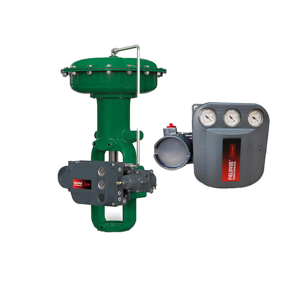
Diagnostics on Fisher FIELDVUE digital valve controllers centre on ValveLink software and NAMUR NE 107 status classification. They can monitor instrument air, leakage, friction, dead band and calibration online without interrupting the process. This article follows the sequence of diagnostic system and levels, common symptoms, alarm and status signals, and tools and procedures, to set out a general approach to troubleshooting. It also clearly separates diagnostic level codes from model-specific fault codes. I. Product Positioning
The microprocessor inside a smart positioner runs, analyses and stores diagnostic tests. Using pressure, temperature and travel sensors plus internal readings, it produces graphical representations of valve performance and health with recommended actions. Diagnostic information is intended to assess the health of the whole control valve assembly, not only the positioner itself. Data obtained via online search. Sources: Emerson official "Control Valve Diagnostics" web page; Fisher FIELDVUE DVC6200 and DVC7K official technical data.
II. Diagnostic System and Level CodesThe DVC6200 series is split into variants by protocol and safety duty. Diagnostic levels depend on the model and order code and must not be transferred between models:
NE 107 classifies device status into four categories: Failure (F), Out of Specification (S), Maintenance Required (M) and Check Function (C). The positioner passes status bits to the control system over HART, FF or PA, with local indicators and ValveLink showing the same information. The exact definition of each diagnostic level and the order code positions are subject to the official manual of the model in use. Source: Fisher official positioner selection document, diagnostic level code table; Emerson official control valve diagnostics material; NE 107 status classes per NAMUR recommendation. III. Common Symptoms and Handling
Data obtained via online search. Sources: Emerson official control valve diagnostics material (in-service diagnostics can detect instrument air quality, leakage, restricted supply pressure, excessive friction, dead band and loss of calibration); Fisher smart positioner official diagnostic data. Specific fault codes and procedures are subject to the official manual of the model in use; fault codes from other brands must not be applied to Fisher devices. IV. Alarm Currents and Status Signals
"Handling codes" should be understood at two levels: the ordering and configuration level (diagnostic level codes such as AC, HC, FD and HCFD), and the operating level (model-specific fault codes). The latter are defined by model and firmware version and must be checked in the official manual of that model; E-series codes from other positioner brands must not be applied to Fisher equipment. Source: Fisher DVC7K official technical data; Emerson control valve diagnostics material; NE 43 and NE 107 per NAMUR recommendations. Specific fault codes are subject to the official manual of the model in use. V. Tools and Operating Practices
Recommended sequence: first check documentation (model, diagnostic level, protocol, wiring), then read online status and alarm records, then select the corresponding diagnostic test by symptom, and finally act on the results and re-test to confirm. Opening the housing or wiring on flameproof or intrinsically safe circuits must follow certification requirements and site work procedures; where explosion protection details are unavailable, write "consult for confirmation". Data obtained via online search. Source: Emerson official control valve diagnostics material (status monitor, valve total scan and step response tests, air leakage, supply pressure, in-service friction and trending, partial stroke test). VI. Selection Guide and Common ModelsSelection guide: Diagnostic capability is determined first by model and protocol: for HART check the HC / AC level of the DVC6200H, for FF check the FD level of the DVC6200f, for SIS applications check the PST and safety functions of the DVC6200 SIS, and note that the DVC7K offers device advice at the device and configurable solid-state switches. Then confirm whether ValveLink software and the required diagnostic level are available on site, otherwise advanced diagnostic data cannot be read. When troubleshooting, read the NE 107 status and active alarms first, choose tests by symptom, then consult the fault code table of the specific model; never transfer codes across brands. Hazardous area wiring and housing opening are subject to the nameplate, certificates and official manual. Common models: DVC6200 (HART, with HC / AC levels), DVC6200f (FF, FD level), DVC6200p (PROFIBUS PA), DVC6200 SIS (safety instrumented systems with PST), DVC7K (device advice at the device and two solid-state switches), DVC2000 (economy type); supporting tools are ValveLink software and certified communication devices. If a positioner in your plant is raising alarms, oscillating or losing communication, or you want to confirm the diagnostic level of a device and whether a software upgrade is needed, please feel free to contact us. We can work through the diagnostic path and handling steps together using the model, protocol and alarm records. Orders & InquiriesBaoman Industrial Technology (Chengdu) Co., LtdTel: +86 028-60220547 | Email: info@bit-cd.com Address: Room 1108, Building A, Tingbiao Central Plaza, No. 158 Erxianqiao East Road, Chenghua District, Chengdu, Sichuan Province, China The information above is not guaranteed to remain valid at all times. Subsequent changes will not be notified separately. Please confirm the latest information at the time of inquiry. |