The Fisher 4211 is an electronic position transmitter in the 4200 series. It senses the position of a sliding-stem or rotary actuator through a potentiometer mechanically coupled to the device and converts it into a 4-20 mA feedback signal. The 4211 is the transmitter-only version, without high or low position switches. This article covers its construction, working principle, technical data, wiring and installation points, and the replacement relationship after the 4200 series was discontinued.
I. Product Positioning
| Item | Description |
|---|
| Brand | Fisher (Emerson) |
| Series | Fisher 4200 series electronic position transmitters (4211 is the transmitter-only model) |
| Function | Senses the position of sliding-stem or rotary actuators, vents, dampers or other devices and sends a 4-20 mA signal to an indicator, control system or PLC |
| Sensing element | Precision film-element potentiometer in the standard unit; precision multi-turn wirewound potentiometer in the long-stroke unit |
| Output / communication | 4-20 mA analog plus switch indication (4211 has 4-20 mA only, no position switches); no digital communication |
| Product status | The 4200 series was discontinued in 2025 and replaced by the FIELDVUE 4400 digital position transmitter; repair kits for installed units remain available |
| Main manuals | Fisher 4200 Instruction Manual D200354X012 (2018-08); hazardous area supplements D104308X012 (CSA), D104309X012 (FM), D104310X012 (ATEX), D104311X012 (IECEx) |
The 4200 series offers three configurations: transmitter only, transmitter with integrated high / low position switches, and position switches only. The 4211 is the first type, with output and travel ranges determined by the type number and Table 2 of the official manual. The series isolates the field wiring compartment from the electronics compartment so moisture entering through the conduit ports cannot reach the electronic circuits.
Data obtained via online search. Sources: Emerson official Fisher 4211 Electronic Position Transmitter product page; Fisher official manuals D200354X012, D104308X012, D104309X012, D104310X012 and D104311X012.
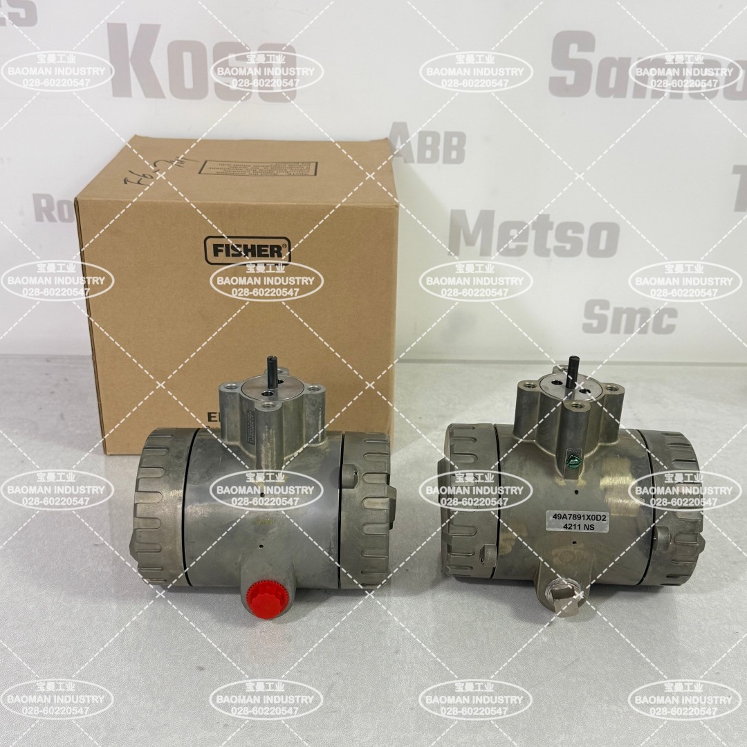
Official product image, for selection reference only
II. Construction and Working Principle
| Stage | Construction and function |
|---|
| Mechanical input | Once mounted, the potentiometer shaft is mechanically connected to the device to sense motion. For sliding-stem service a multi-turn potentiometer is coupled to a travel transducer assembly to sense linear stem motion; for rotary service it can be connected directly to the rotating shaft. |
| Sensing element | The standard unit uses a precision film-element potentiometer and the long-stroke unit a precision multi-turn wirewound potentiometer. Linearity is optimized by matching the sensing element span to the application travel. |
| Signal conversion | The potentiometer converts mechanical position into a resistance / voltage change, and the electronics convert it into a 4-20 mA DC output proportional to travel. |
| Travel alarms (other models) | Models with travel limit alarms use comparator circuits that monitor the sense potentiometer voltage output; the electronic travel limit alarm has an adjustable deadband up to 10 percent of maximum span. The 4211 does not have this feature. |
| Circuit design | A hybrid electronic design combines discrete components and integrated circuits. The field wiring compartment is physically isolated from the electronics compartment for reliability. |
The 4200 series output action can be configured as direct (output increases with travel) or reverse. Zero and span limits are given in Table 3 of the official manual. After installation, zero and span calibration is required so that 4 mA corresponds to the lower travel limit and 20 mA to the upper travel limit.
Data obtained via online search. Sources: Emerson official Fisher 4211 product page; Fisher official manual D200354X012 (zero and span limits in Table 3).
III. Technical Data
| Parameter | Specification |
|---|
| Input signal | Single potentiometer (standard); dual potentiometer only on the 4215, providing additional electrical isolation between transmitter and switch circuits |
| Output signal | 4-20 mA DC (4210 / 4211 / 4215 / 4220 / 4221) |
| Output current limit | 30 mA DC (maximum) |
| Reference accuracy | +/-1% of output span, including hysteresis, linearity and dead band |
| Repeatability | +/-0.25% of span |
| Power requirement, transmitter only | 11-30 V DC / 20 mA max; 24 V DC nominal recommended |
| Power requirement, switch models | With transmitter and position switches: 20-30 V / 80 mA max; position switches without transmitter: 20-30 V / 50 mA max |
| Position switch relays (other models) | Two SPDT; contacts rated 5 A at 30 V DC or 120 V AC (resistive); rated life 100,000 operations |
| Ambient temperature | Operating -40 to +71 degrees C (-40 to +160 degrees F); storage / transport -50 to +80 degrees C (-60 to +180 degrees F) |
| Relative humidity | 10% to 95% (operating and storage / transport) |
| Temperature effect | For every 38 degrees C (100 degrees F) change: zero shift max +/-0.5%, span shift max +/-0.75% of span |
| Power supply effect | Output change less than +/-0.1% for supply variation |
| Enclosure protection | NEMA 4X; CSA Enclosure 4X; IP66 |
| EMC (4211 / 4221) | Compliant with EN 61326-1:2013; immunity for industrial location, emission Class A |
| Approximate weight | Transmitter without mounting bracket about 1.8 kg (4 lb) |
Source: Fisher official manual D200354X012; parameters are subject to the latest official manual.
IV. Wiring and Installation Points
| Item | Key points |
|---|
| Loop structure | The 4211 is a two-wire 4-20 mA transmitter connected in an 11-30 V DC loop; it draws at most 20 mA, with 24 V DC nominal recommended. |
| Compartment isolation | The field wiring compartment is separate from the electronics compartment. Conductors enter the wiring compartment through conduit entries before reaching the terminals, so moisture does not reach the electronics directly. |
| Polarity | Connect the supply / signal positive and negative terminals as shown in the manual; recheck polarity and wiring before power-up. The specific terminal numbers are given in the wiring diagram of manual D200354X012. |
| Cable and shielding | Use conductors suitable for site practice; shielding and grounding shall follow the manual and site instrumentation grounding requirements. Do not assume terminal numbers. |
| Mechanical mounting | Couple the potentiometer shaft securely to the actuator stem or shaft, avoiding backlash and overstress. Standard travel is up to 105 mm (4.125 in) and long stroke up to 610 mm (24 in). |
| Calibration | Perform zero and span calibration after mounting. Zero and span limits are given in Table 3 of the manual. Configure output action as direct or reverse as required. |
| Hazardous area wiring | Intrinsically safe, explosion proof, dust ignition proof and non-incendive options correspond to CSA / FM / ATEX / IECEx certifications. Wiring must follow the nameplate and certificate requirements. Intrinsically safe (Ex ia) and flameproof (Ex d) are different protection concepts and must not be confused; where data is unavailable, write "consult for confirmation". |
The 4211 has no position switch output. If both 4-20 mA feedback and high / low limit switches are needed, specify the 4210 (transmitter plus position switches) or the 4215 (dual potentiometer, transmitter plus position switches) rather than adding switches to a 4211.
Data obtained via online search. Sources: Emerson official Fisher 4211 product page; Fisher official manual D200354X012 and related hazardous area supplements. Specific terminal numbers and wiring diagrams are subject to the official manual.
V. Model Configuration and Generational Replacement
| Model | Configuration | Travel category |
|---|
| 4210 | Transmitter plus electrical position switches | Standard travel |
| 4211 | Transmitter only, no position switches | Standard travel |
| 4212 | Position switches only | Standard travel |
| 4215 | Transmitter plus position switches, dual potentiometer | Standard travel |
| 4220 / 4221 / 4222 | Long-stroke versions of 4210 / 4211 / 4212 | Long stroke |
The 4200 series was formally discontinued in 2025 and replaced by the FIELDVUE 4400 digital position transmitter. The 4400 uses a linkless non-contact Hall-Effect feedback arrangement, requires a separately ordered magnet strip and a dedicated mounting kit, and cannot reuse 4200 brackets or calibration procedures. Repair kits for installed 4200 units remain orderable, but new projects should specify the 4400 directly.
Source: Fisher official manual D200354X012 and Fisher 4400 product bulletin D104739X0CN; discontinuation and replacement status are subject to official Emerson announcements.
VI. Selection Guide and Common Models
Selection guide: First decide the generation by project stage: new projects should use the FIELDVUE 4400, while installed 4200 units are maintained with original repair kits. Then choose the configuration by switch requirement: 4211 for 4-20 mA feedback only, 4210 or 4215 when high / low limit switches are also needed, and 4212 for switches only. Next determine standard or long stroke (42xx series) and the mounting kit from actuator travel / rotation. Then check power supply, load, environment and enclosure protection. Finally select the hazardous area certification (CSA / FM / ATEX / IECEx). The 4211, 4210 and 4215 have different output and switch configurations, so their order models cannot be interchanged.
Common models: 4211 (transmitter only, standard travel), 4210 (transmitter plus position switches), 4212 (position switches only), 4215 (dual potentiometer, transmitter plus position switches), and the long-stroke 4220, 4221 and 4222. The replacement product is the FIELDVUE 4400 digital position transmitter.
If you need independent valve position feedback, or want to understand how to transition from the discontinued 4211 to the current 4400, please feel free to contact us. We can check the model and mounting method together against your travel / rotation, switch requirement and site certification.
Orders & Inquiries
Baoman Industrial Technology (Chengdu) Co., Ltd
Tel: +86 028-60220547 | Email: info@bit-cd.com
Address: Room 1108, Building A, Tingbiao Central Plaza, No. 158 Erxianqiao East Road, Chenghua District, Chengdu, Sichuan Province, China
The information above is not guaranteed to remain valid at all times. Subsequent changes will not be notified separately. Please confirm the latest information at the time of inquiry.

 简体中文
 ENGLISH

