简体中文
 ENGLISH
| Fisher DLC3010 / DLC3020F Digital Displacer Level Controllers - Principle & Appl | ||||||||||||||||||||||||||||||||||||||||||||||||||||||||||||||||||||||||||||||||
| Release time:2026-11-21 02:05:02 | Views: | ||||||||||||||||||||||||||||||||||||||||||||||||||||||||||||||||||||||||||||||||
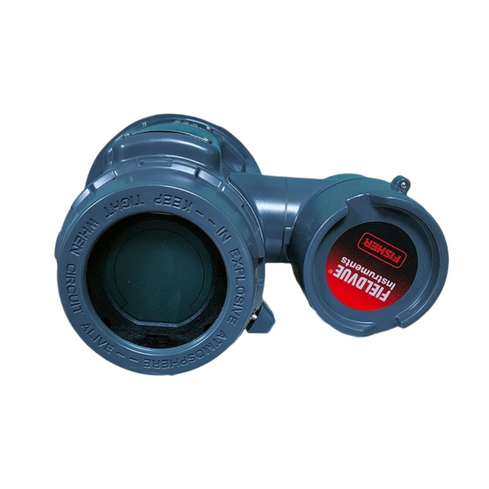
The Fisher FIELDVUE DLC3010 and DLC3020f are both digital level controllers based on a 249 displacer and torque tube sensor, but their communication schemes are completely different: the DLC3010 uses 4-20 mA plus HART, while the DLC3020f uses FOUNDATION Fieldbus with no independent analog output. This article covers the measurement principle, construction, key specifications, point-by-point differences and typical applications of both instruments, to support the right choice for a given protocol and function requirement. I. Product Positioning
The DLC3010 is a microprocessor-based digital level controller that directly replaces conventional pneumatic and electronic level transmitters. Besides the 4-20 mA current signal, it gives access to process, instrument and sensor information at any point on the loop via HART. The DLC3020f uses the same displacer and torque tube sensing platform but has FOUNDATION Fieldbus as its only communication interface; in addition to reporting the process variable (PV), it can act as a PID controller or a level switch, and supports dynamic temperature compensation to maintain PV accuracy after density compensation. Data obtained via online search. Sources: Emerson official manuals D102748X012 (DLC3010 Instruction Manual, 2018-05) and D104329X012 (HART Field Device Specification, 2022-05); Emerson official Fisher DLC3020f product page; Fisher official manuals D103434X012 and D103433X012.
II. Construction and Working PrincipleBoth instruments share the same measurement chain, with four stages:
Process temperature compensation is an optional feature on both. A 2-wire or 3-wire 100 ohm platinum RTD can be connected at terminals marked Rs, R1 and R2. Once the user enters a density-versus-temperature table, the RTD measurement drives density compensation to keep the level / interface PV accurate. If no RTD is installed, the compensation table can be driven by a manually entered process temperature. The DLC3010 also has an internal electronics temperature sensor for Hall element flux and sensitivity compensation. Source: Fisher official manuals D102748X012, D104329X012 and D103434X012. III. Technical Data: DLC3010 vs DLC3020f
Data obtained via online search. Sources: Emerson official manuals D102748X012 and D104329X012 (DLC3010); Emerson official Fisher DLC3020f product page and Fisher manual D103434X012 (DLC3020f). Additional source URL: https://www.emerson.com/documents/automation/im-supplement-hart-field-device-specification-fieldvue-dlc3010-digital-level-controller-supported-product-en-11744406.pdf . Parameters are subject to the latest official data. IV. Key Differences and Model Distinctions1. Protocols are not interchangeable: the DLC3010 supports only HART and 4-20 mA and cannot join an FF bus segment; the DLC3020f supports only FOUNDATION Fieldbus and cannot replace the 4-20 mA loop of the DLC3010. 2. Different functions: the DLC3010 is a transmitter in the system, while the DLC3020f can be configured as a transmitter, PID controller or level switch, performing control and switching logic on the bus side. 3. Different power and loading: the DLC3010 requires a 12-30 V DC loop and must meet HART impedance (230-600 ohms); the DLC3020f uses 9-32 V DC at 17.7 mA, is polarity independent and follows FF bus power and segment parameters. 4. Different accuracy figures: the DLC3020f specifies +/-0.15% overall accuracy, while the DLC3010 independent linearity is graded by displacer configuration; the two numbers must not be compared directly. 5. Product generations: the Fisher level line also includes the DLC3100 / DLC3100 SIS (4-20 mA plus HART, D104213X0CN) as a later HART platform. Select among the DLC3010, DLC3020f and DLC3100 by protocol requirement, and do not infer product generation from the model number alone. Source: Fisher official manuals D102748X012, D104329X012, D103434X012 and D104213X0CN; confirm the complete order code with the official selection tool. V. Applications and Typical Pairings
Source: Fisher official manuals D102748X012 and D103434X012; selection limits are subject to the official manual. VI. Selection Guide and Common ModelsSelection guide: First fix the communication by control system: choose the DLC3010 for a 4-20 mA / HART loop, the DLC3020f for a FOUNDATION Fieldbus segment, and evaluate the DLC3100 / DLC3100 SIS for a newer HART platform. Then select the 249 sensor model, displacer size and material by measured variable (level, interface, density) and process temperature, checking the density difference for interface service. Next decide on RTD temperature compensation, thermal isolator, M20 adapters and display options. Finally select the hazardous area certification (CSA / FM / ATEX / IECEx). The DLC3010 and DLC3020f cannot replace each other; their model numbers are similar but their communication and output architectures are completely different. Common models: DLC3010 digital level controller (HART, two-wire 4-20 mA, with 249 series sensors); DLC3020f fieldbus digital level controller (FF, configurable as transmitter, PID controller or level switch); related products include the DLC3100 and DLC3100 SIS (HART), the L2 / L2e / L2sj / L2t level controllers and the 249 displacer sensors. If you are specifying a level or interface instrument for a vessel, or want to confirm whether your site uses a HART loop or an FF bus and how to pair the DLC3010 and DLC3020f, please feel free to contact us. We can check the model and ordering information together against your protocol, density difference and 249 sensor configuration. Orders & InquiriesBaoman Industrial Technology (Chengdu) Co., LtdTel: +86 028-60220547 | Email: info@bit-cd.com Address: Room 1108, Building A, Tingbiao Central Plaza, No. 158 Erxianqiao East Road, Chenghua District, Chengdu, Sichuan Province, China The information above is not guaranteed to remain valid at all times. Subsequent changes will not be notified separately. Please confirm the latest information at the time of inquiry. |