简体中文
 ENGLISH
| Flowserve Logix Positioners - Common Faults & Troubleshooting | |||||||||||||||||||||||||||||||||||||||||||||||||||
| Release time:2026-11-21 00:50:35 | Views: | |||||||||||||||||||||||||||||||||||||||||||||||||||
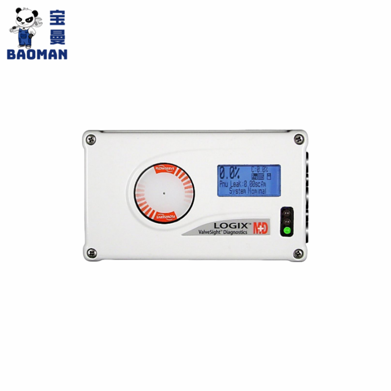
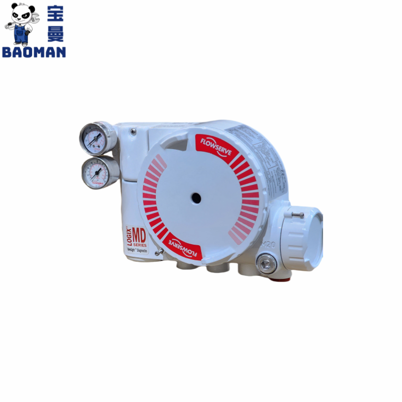
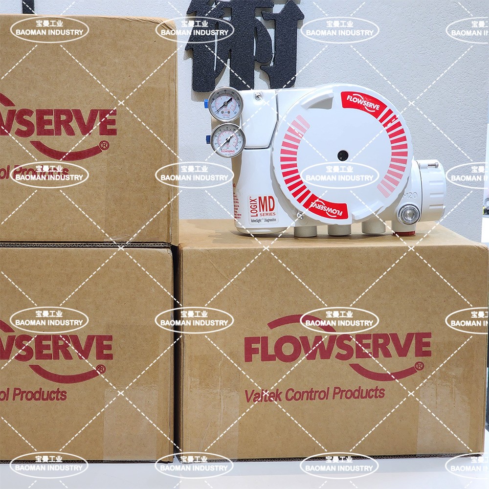
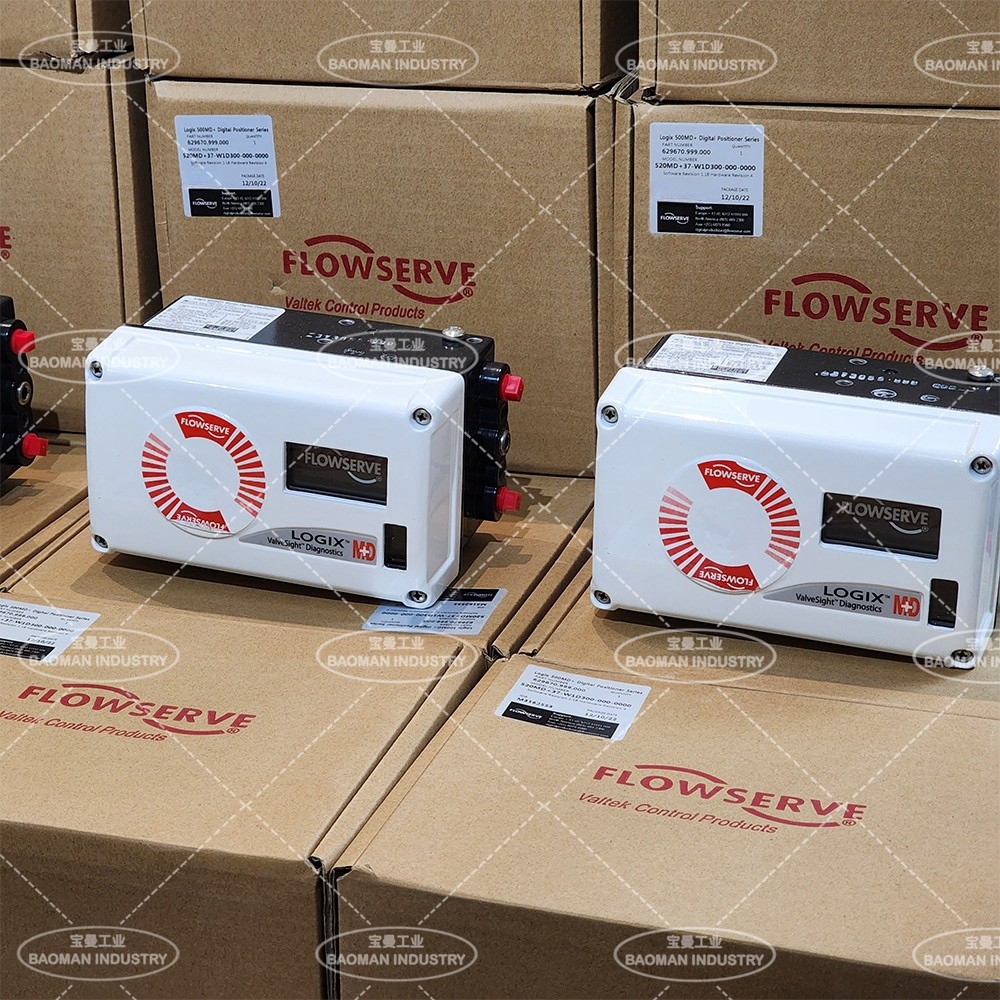
Flowserve Logix positioners, including the Logix 520MD+ and Logix 3200MD series, allow local setup, response speed adjustment and calibration. Based on the official Logix 520MD / 3200MD user manuals, this article covers the control panel, wiring terminals, configuration switches and operating principle, together with common field faults, possible causes and corrective actions, for reference in selection, commissioning and maintenance. I. Positioner Series OverviewLogix 520MD+ series positioner
Logix 3200MD series positioner
Source: Official Flowserve Logix 520MD / 3200MD user manuals (confirm the specific document number with the manufacturer). Parameters are subject to the latest official data. II. Logix 520MD Positioner Overview and Control PanelThe Logix 520MD positioner can be set up, tuned for response speed and calibrated locally, without additional tools or a configurator. Control Panel Components
Wiring Terminals
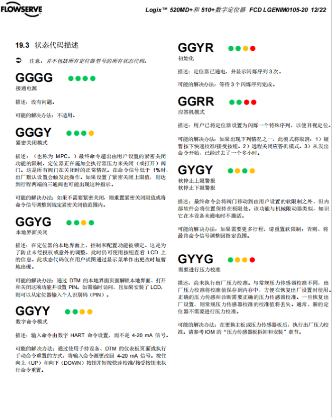
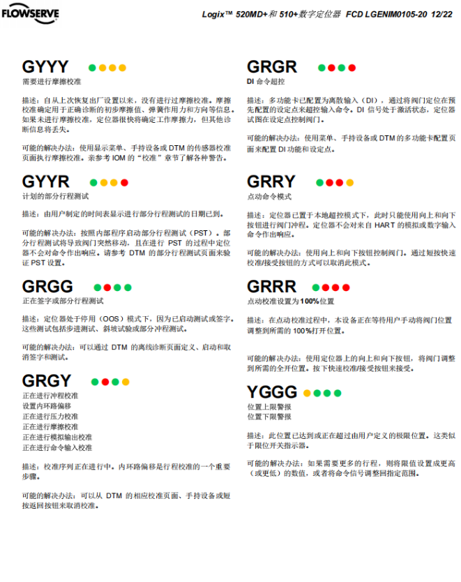
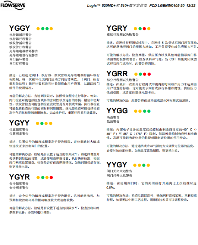
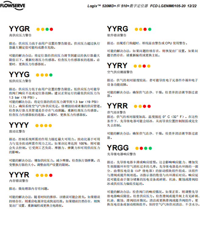
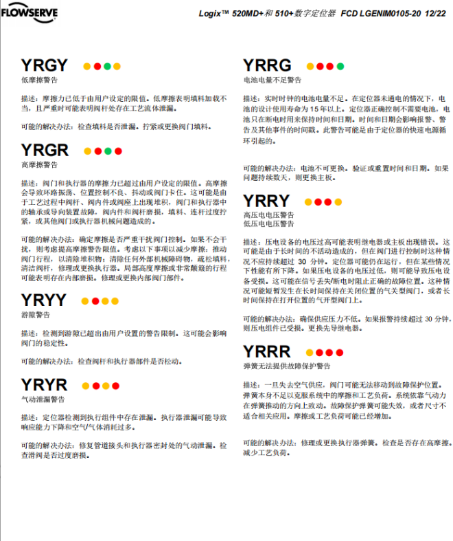
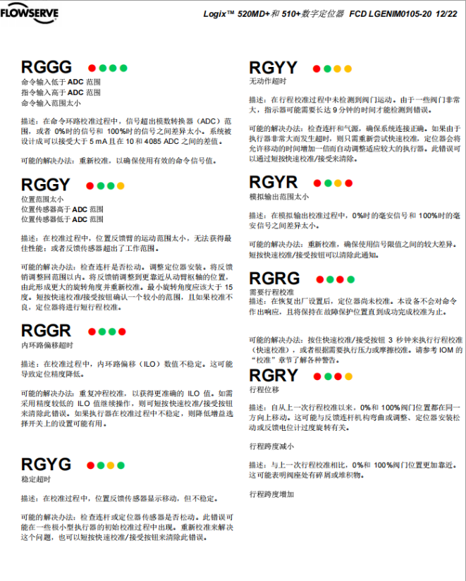
* Limit switches 1 and 2 are on separate circuit boards. Status Code Description
Source: Official Flowserve Logix 520MD / 3200MD user manuals (confirm the specific document number with the manufacturer). III. Configuration Switches1. Pneumatic Action
2. Closed-Position Signal Setting
3. Position Characteristic
4. Auto-TuningWhen enabled, auto-tuning runs each time the Quick-Cal button is pressed, and the gain is calculated from the gain switch setting. 5. Stability Switch
6. Travel Calibration Mode
Source: Official Flowserve Logix 520MD / 3200MD user manuals (confirm the specific document number with the manufacturer). IV. Operating PrincipleAn electrical signal (4-20 mA) is fed to the microprocessor and compared with the measured valve position. The control algorithm drives the piezoelectric valve, which controls the output pressure of the pneumatic amplifier and moves the actuator. As the valve position approaches the commanded position, the output decreases and finally stabilizes at the set position. If the valve position feedback signal cannot return in time, continuous output pressure will result and the valve will not reach its position; check the connections and perform travel calibration. Source: Official Flowserve Logix 520MD / 3200MD user manuals (confirm the specific document number with the manufacturer). V. Common Faults and Troubleshooting
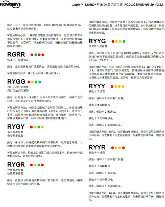
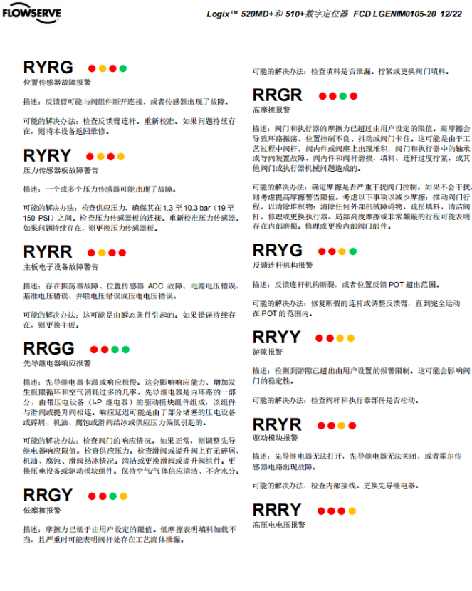
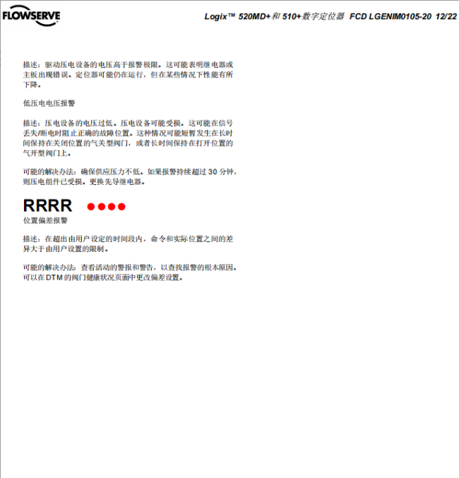
1. Valve Will Not Close Tightly or Cannot Fully OpenExample: FV1027 2. Valve Stem OscillationExample: PV1049 Additional figures from the original document:
Source: Official Flowserve Logix 520MD / 3200MD user manuals (confirm the specific document number with the manufacturer). VI. Model Description
Specific ordering codes, communication protocols, hazardous-area certifications and official document numbers should be confirmed against official Flowserve selection data and with the manufacturer. Source: Official Flowserve Logix 520MD / 3200MD user manuals (confirm the specific document number with the manufacturer). VII. Selection Guide and Common ModelsSelection guide: Determine the pneumatic action first, ATO (air-to-open) or ATC (air-to-close), and set the closed-position signal accordingly (normally 4 mA for air-to-open actuators and 20 mA for air-to-close actuators). Then determine the position characteristic, stability switch and travel calibration mode (auto or jog) according to mounting and feedback conditions. Finally confirm the specific model against site communication, diagnostic and maintenance requirements. The faults and corrective actions listed in this article apply to the Logix 520MD / 520MD+ and Logix 3200MD; specific ordering codes and document numbers should be confirmed with the official Flowserve manuals and the manufacturer. Common models: Logix 520MD+ (series name in the original text), Logix 520MD (as written in the overview of the original text), Logix 3200MD series positioner. If you are troubleshooting a positioner on a valve in the field, or want to confirm the configuration switches and calibration settings of the Logix 520MD / 3200MD, please feel free to contact us. We can review the fault cause and corrective steps together against your valve action, signal and site conditions. Orders & InquiriesBaoman Industrial Technology (Chengdu) Co., LtdTel: +86 028-60220547 | Email: info@bit-cd.com Address: Room 1108, Building A, Tingbiao Central Plaza, No. 158 Erxianqiao East Road, Chenghua District, Chengdu, Sichuan Province, China The information above is not guaranteed to remain valid at all times. Subsequent changes will not be notified separately. Please confirm the latest information at the time of inquiry. |